- Difficulty
- Beginner hardware
- Time
- 30 min
- Guidance reference
- App 0.2.0 beta · firmware 0.6.1 · PBLE/1
Historical screenshots retain the firmware versions and App state captured at the time; they have not been retaken on firmware 0.6.1.
Prerequisites
- The Hardware safety lesson, exact board documentation, and reviewed components
Outcomes
- Configure pins explicitly for common digital and bus examples
- Choose a bounded example whose capability matches the circuit
- Stop the program and restore a safe hardware state
Release-aware guidance
Compatibility
The guidance reference above is not a promise about the installer currently being served. Confirm the active version, exact profile, and enabled action on the current firmware and flash page before provisioning or changing hardware.
Qualified firmware describes firmware evidence. The table below describes this lesson's scope; it does not turn designed compatibility into hardware validation.
| Firmware profile | Lesson scope |
|---|---|
Classic ESP32 (4 MiB)esp32-4mb | Designed for this profile |
ESP32-S3 N16R8 · lean genericesp32-s3-n16r8 | Designed for this profile |
Waveshare ESP32-S3-LCD-1.47Bwaveshare-esp32-s3-lcd-147b | Designed for this profile |
ESP32-C3 (4 MiB)esp32-c3-4mb | Designed for this profile |
Raspberry Pi Pico 2 Wrpi-pico2-w | Designed for this profile |
GPIO, ADC, PWM, I2C, and SPI examples are designed across the five profiles only after configuration review. NeoPixel examples are designed for the four ESP profiles and are not applicable to Pico 2 W in this development snapshot.
Before you begin
Complete Hardware safety first. This lesson supplies no default pins and does not choose a pin from the connected chip. Set every role from your exact board documentation, inspect the complete example at its immutable source link, and keep the circuit powered off while wiring.
One observed ESP32-C3 configuration context
Board C81A reported the esp32-c3 runtime token in this maintained physical session. That observation helps confirm the connected runtime, but exact carrier documentation must still supply every pin and electrical choice.
PyBLE-C81A Generic ESP32-C3 · 4 MiB
Ready observation Runtime token ·
esp32-c3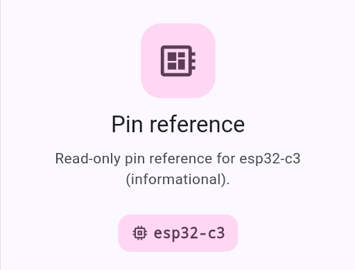
Maintained physical-session record: ESP32-C3. Revision, flash capacity, and pin choices still come from the physical board record and exact documentation.
Review, observe, restore
- Review
Confirm pin roles, voltage, current, boot conflicts, protection, and shared ground.
- Observe
Run one finite effect with Console visible and Stop immediately available.
- Restore
Leave outputs safe, deinitialize buses, power down, and remove temporary wiring.
Capability progression
GPIO
External LED, button input, and a two-pin combined exercise.
PWM
A protected external LED with a finite low-duty fade.
ADC
A capped set of raw and scaled readings inside the input range.
I2C
An explicitly configured software bus and finite address scan.
SPI
An explicitly configured software bus and finite loopback.
NeoPixel
A dim finite pixel sequence on reviewed ESP hardware and power.
Change one variable at a time
Begin with one component and the shortest bounded example. Record the exact configuration and observation before adding another capability. A traceback or unexpected physical effect is a Stop condition, not a prompt to try random pin numbers.
Follow in order
Tutorial steps
Create an explicit configuration worksheet
Choose one capability and write down every role it needs. Set each GPIO number or exact pin name from your exact board documentation, plus mode, pull, voltage, current, shared peripheral, and cleanup. PyBLE does not choose a pin for you.
Stop if: any role lacks an exact documented pin, electrical limit, wiring path, or safe cleanup state.
Start with bounded digital GPIO
For an external LED, use the reviewed output pin, polarity, and current-limiting resistor. For a button, use the reviewed input and the example's documented pull/active level. For Button Controls LED, configure two distinct compatible pins.
Expected: a finite LED sequence or bounded button-transition report matches the circuit, then the output returns to its safe state.
Add PWM only to a suitable output
Confirm the chosen output supports PWM and the load is electrically appropriate. Use the example's bounded low-duty fade rather than driving an unknown load directly from a GPIO.
Expected: the protected LED changes smoothly for the finite sequence and PWM is deinitialized or the output is left safe.
Sample ADC within its input range
Verify the ADC-capable pin and the board's permitted analog input voltage. Connect only a source that stays inside that range and shares the intended ground; never use ADC sampling as a way to discover safe voltage.
Stop if: the source can exceed the documented ADC range, floats unpredictably, or lacks a reviewed common reference.
Configure I2C signal and power roles
Set explicit SDA and SCL pins, a conservative frequency, peripheral supply voltage, common ground, address expectations, and appropriate pull-ups. Run only a bounded I2C scan on the reviewed bus.
Expected: Console reports a finite address list or a truthful empty result without changing peripheral state.
Wire the finite SPI loopback deliberately
Configure explicit SCK, MOSI, and MISO pins from exact documentation. For the loopback exercise, connect only the documented loopback path with power off; do not attach an unknown SPI peripheral as a substitute.
Expected: the received finite payload matches the transmitted bytes and the software SPI object is deinitialized.
Use NeoPixel only inside the ESP design boundary
On one of the four ESP profiles, configure the exact data GPIO, pixel count, low brightness, supply, logic-level requirements, and shared ground for a WS2812-compatible pixel or strip. This capability is not designed for the Pico 2 W profile in the reviewed snapshot.
Stop if: the profile is Pico 2 W, the pixel supply or logic level is uncertain, or the strip current exceeds the reviewed power plan.
Stop and perform visible cleanup
Compare the effect and Console output with the bounded plan. Press Stop on any mismatch. Finish the example's
finallycleanup where provided, set outputs and pixels off, deinitialize buses or PWM, remove peripheral power, and only then alter wiring.Expected: the bounded test is complete, outputs are safe, buses are released, pixels are dark, and the circuit is unpowered before rewiring.
Need recovery help?
Stop at the current step, record the exact profile, board identity, app and firmware versions, and the first useful error. Then use the PyBLE support and recovery guide.